1 YourResearchProject Pty Ltd, PO Box 143, Red Hill, QLD 4059, Australien
2 Griffith University, 1 Parklands Dr, Southport, QLD 4215, Australien
3 University of the Sunshine Coast, 90 Sippy Downs Dr, Sippy Downs, QLD 4556, Australien
4 Queensland University of Technology, 2 George St, Brisbane, City, QLD, 4000, Australien
5 APC Prosthetics Pty Ltd, Suite 1, 170–180 Bourke Rd, Alexandria, NSW 2015, Australien
6 Sum of Squares – Statistical Consulting, Essener Str. 100, 04357 Leipzig, Deutschland
7 ÖSSUR, R&D, Medical Office, Grjothals 1–5, Reykjavik, Island
%BW = Prozentsatz Körpergewicht
%GC = Prozentsatz Gangzyklus
%SUP = Prozentsatz Stützphasen
AP = Anterior-posteriore Achse
BAP = Knochenverankerte Prothese
BW = Körpergewicht
ESAR = Energiespeichernder und ‑rückgebender Fuß
F = Kraft
GC = Gangzyklus
LG = Längsachse
M = Moment
ML = Mediolaterale Achse
MPK = Mikroprozessorkontrolliertes Knie
N = Anzahl Gangzyklen
PV = Prozentsatz der Abweichungen
SUP = Stützphasen des Gangzyklus
TFA = Person mit transfemoraler Amputation
Einleitung
Da eine Prothese für die Aufrechterhaltung der Lebensqualität von Personen mit transfemoraler Amputation (TFA) von entscheidender Bedeutung ist, wählen Versorger am ehesten solche Schaft‑, Knie- und Fußkomponenten aus, die eine maximale Funktionalität ermöglichen1. Leider sind die Weichteile des Stumpfes nur begrenzt in der Lage, den mechanischen Belastungen standzuhalten, die von der Prothese während der Gewichtsbelastung durch den Schaft übertragen werden. In der Praxis könnte die Schnittstelle zwischen Stumpf und Schaft zu erheblichen Beschwerden aufgrund von Hautschädigungen führen und eine frühe, vorübergehende oder möglicherweise auch endgültige Ablehnung der Prothese zur Folge haben2.
Alternativ können TFA mit knochenverankerten Prothesen (BAP) ausgestattet werden, die an einem osseointegrierten Implantat befestigt sind, das chirurgisch in den verbleibenden Oberschenkelknochen eingesetzt wird3 4. Mehrere Studien haben gezeigt, dass transfemorale BAP die Funktionen und die gesundheitsbezogene Lebensqualität verbessern können, insbesondere bei jungen und aktiven Menschen, die unter sehr großen Schaftproblemen leiden5 6 7 8 9 10. Das Management von Weichteilresten sowie die Risiken von Infektionen, Lockerungen, periprothetischen Frakturen und Brüchen von osseointegrierten Implantatteilen werden von den Behandlungsteams als akzeptabel angesehen, obwohl diese bisher noch nicht zufriedenstellend gelöst sind11 12 13 14 15. Vorläufige gesundheitsökonomische Analysen weisen auf die Kosteneffizienz von BAP im Vergleich zu Schaftprothesen aus Sicht der staatlichen prothetischen Versorgung hin16 17 18 19.
Verordnung von Prothesenpassteilen
Die Vor- und Nachteile der osseointegrierten Implantate vermischen sich durch Anpassung der Prothesen während der Rehabilitation und danach20 21 22 23 24 25. Bei maßgeschneiderten Empfehlungen von klinischen Teams für Passteile werden individuelle Empfehlungen, die Art des Implantats, die Anweisungen des Herstellers, die Lebensweise und die Kosten berücksichtigt26. Ursprünglich wurden mechanisch passive Komponenten mit Grundfunktionen empfohlen, wie einachsige oder polyzentrische hydraulische Knie und multiaxiale Fuß- und Knöchelgelenkseinheiten27 28. Heutzutage dagegen werden immer häufiger fortschrittliche Komponenten wie mikroprozessorgesteuerte Kniegelenke (MPK) und energiespeichernde Fußpassteile (ESAR) verordnet29 30 31 32. Die Verordnung dieser Passteile wird von einigen Teams sogar als Best-Practice angesehen33.
Das Belastungsprofil
Laut Frossard et al. 34 35 36 und Robinson et al. 37 ergeben sich die biomechanischen Vorteile dieser Passteile (z. B. verbesserte Funktionen, geringere Exposition gegenüber unerwünschten Ereignissen) aus dem von ihnen erzeugten Belastungsprofil, das dem wiederholten Muster jener Kräfte und Momente entspricht, die während der täglichen Aktivitäten auf den Bereich der drei anatomischen Achsen des osseointegrierten Implantats einwirken.
Grundsätzlich könnten mit MPK und ESAR ausgestattete BAP die Stabilität (z. B. Stand- und Schwungkontrolle), die Gehfähigkeit (z. B. großer Bewegungsumfang, mechanisch angetriebenes Abstoßen), die Dämpfung bei übermäßigen Belastungen im Rahmen alltäglicher Aktivitäten (z. B. automatische adaptive Stand- und Schwungphasen) erhöhen und das Sturzrisiko verringern (z. B. automatische Stolperkorrektur) 38 39 40 41 42 43. Eine mögliche Hypothese wäre, dass diese Funktionen ein Belastungsprofil innerhalb der Goldilocks-Zone für das osseointegrierte Implantat erzeugen können. Wie von Pitkin und Frossard44 beschrieben und im Anhang näher erläutert, bezieht sich dieses Konzept der Goldilocks-Zone auf den Bereich, in dem die auf das Implantat und den Stumpf ausgeübten mechanischen Beanspruchungen (z. B. die Größenordnung der Kräfte und Momente) innerhalb eines Bereichs liegen, der passend dafür ist, die Stabilität der Knochen-Implantat-Verbindung zu erhalten45. Es wird davon ausgegangen, dass die Belastung durch moderne BAP-Passteile eher innerhalb eines sicheren, weniger risikoreichen Bereichs liegt (z. B. „geeignete Belastung“ für eine stabile Osseointegration), sodass die Knochen-Implantat-Verbindung nicht geschädigt wird (z. B. „Unterbelastung“ in Verbindung mit frühzeitiger Lockerung und Infektion, „Überbelastung“, die zum Bruch von Teilen und periprothetischen Frakturen führt).
Belastungsprofil: aktueller Kenntnisstand
Leider konnte diese Hypothese nur teilweise mit dem aktuellen Wissen über das von BAP aufgebrachte Belastungsprofil, das mithilfe der inversen Dynamik geschätzt oder mit einem Sensor gemessen wird, validiert werden46 47 48 49 50 51. Lee et al. 52 53 berichten über einige Belastungsmerkmale beim Gehen sowie beim Auf- und Absteigen von Rampen und Treppen für eine Kohorte von TFA mit Schraubimplantaten und Basiskomponenten (z. B. mechanisch passives Knie, multiaxiales Knöchelgelenk) 54 55 56. Frossard et al. zeigen in einer Einzelfallstudie57, dass das Belastungsprofil anhand einer Reihe von Extrema in der Lage ist, mit mechanischen und MPK-Knien ausgestattete BAP zu unterscheiden58. 2021 haben Frossard et al. die vervollständigten Studienergebnisse publiziert59 60.
Belastungsprofil: Notwendigkeit bei modernen Prothesenpassteilen
Bislang gibt es nur wenige Belege für biomechanische Vorteile von modernen Prothesenpassteilen. Klar ist die Notwendigkeit, ein besseres Verständnis für BAP Belastungsprofile bei täglichen Aktivitäten mit modernen Prothesenpassteile zu erhalten61.
Die Erhebung neuer kinetischer Daten zu Rheo Knee XC und Pro-Flex XC oder zum LP-Prothesenfuß (Össur, Island) ist angezeigt, da sie zu den MPK- und ESAR-Passteilen gehören, die z. B. in Australien für Personen mit osseointegrierten Implantaten häufig empfohlen werden.
Zielsetzung
Im Rahmen der Querschnitts-Kohortenstudie erfolgte die Darstellung eines Belastungsprofils, das auf transfemorale osseointegrierte Implantate durch die mit Rheo Knee XC und Pro-Flex XC oder LP ausgestattete BAP unter Verwendung der Wearable-Sensor-Technologie bei fünf täglichen Aktivitäten ausgeübt wird. Ziel der Studie war 1) zu einem besseren Verständnis der mechanischen Auswirkungen von BAPs mit modernen Prothesenpassteilen auf osseointegrierte Implantate der unteren Gliedmaßen beizutragen und 2) den Bereich und die Variabilität der spatiotemporalen Gangvariablen, die Größenordnung der Belastungsgrenzen sowie den Beginn und die Größenordnung der Extrema darzustellen, die während des standardisierten ebenen Gehens, des Aufsteigens auf und des Absteigens von einer Rampe auftreten.
Frossard beschreibt ergänzend die Goldilocks-Zone, die Position des Sensors in Bezug auf das Implantat und das Erkennen von Extrema62. Darüber hinaus wurden Literaturverzeichnisse und Meta-Analysen durch zusätzliche im Magazin „Data in Brief“ veröffentlichte Informationen sowie die Störfaktoren detailliert beschrieben (Auswahlkriterien, demografische Daten, Amputationsdaten, Protheseninformationen, Verbindungen zwischen Implantat und Sensor, Ausrichtung instrumentierter Prothesen, Position des perkutanen Teils und des Knies in Bezug auf den Sensor, Beschreibung des nicht-experimentellen Aufbaus, Aufschlüsselung der Anzahl der analysierten Schritte pro Aktivität, Belastungsgrenzen sowie Streudiagramme, die die Streuung der ermittelten Extrema zeigen, und Boxplots der Größenordnung der Extrema).
Methoden
Population
Die Teilnehmer wurden von einem lokalen Orthopädietechniker entsprechend der zuvor vorgestellten Auswahlkriterien rekrutiert (z. B. ca. 6–8 cm Bauhöhe für die Anbringung des Sensors, Abschluss der Rehabilitation, Fähigkeit, 200 m selbstständig zu gehen) 63 64 65 66. Es gab keine Ausschlusskriterien hinsichtlich Geschlecht, ethnischer Zugehörigkeit, Körpergröße und Funktionsniveau. Insgesamt 13 TF mit einem nicht von der FDA zugelassenen Press-Fit-Implantat wurden zwischen September 2017 und August 2018 in Sydney, Australien, bewertet (d. h. Integral-Leg-Prosthesis [Eska Orthopedics GmbH, Deutschland]; Osseointegration Prosthetic Limb [Permedica SPA, Italien]) 67.
Jeder Teilnehmer unterzeichnete eine Einwilligungserklärung, die von der Ethikkommission der Forschungseinrichtung genehmigt wurde (Human Research Ethics Committee Zertifikat-Nr. 1600000332, Queensland University of Technology, Brisbane, Australien).
Prothese
Die Teilnehmer wurden mit einer instrumentierten Modularprothese und einem Offset-Adapter, einem iPecsLab-Sensor (RTC Electronics, USA), Rheo Knee XC, Pro-Flex XC oder LP-Fuß und ihrem eigenen Schuhwerk ausgestattet68 69 70. Wir haben uns bewusst für die XC- und LP-Modelle der Pro-Flex-Familie entschieden, die in der Regel für Patienten in Australien empfohlen werden, da sie einer hohen Stoßbelastung standhalten.
Ein qualifizierter und erfahrener Orthopädietechniker führte den statischen Aufbau durch, indem er mithilfe des L.A.S.A.R. Posture (Ottobock, Deutschland) das Zentrum des Kniegelenks etwa drei Zentimeter hinter der vertikalen Linie des Körperschwerpunkts positionierte71. Der Orthopädietechniker stellte die dynamische Ausrichtung und den Widerstand für Knie und Fuß den Präferenzen der Teilnehmer entsprechend ein72. Diese waren daran gewöhnt, mit einer MPK zu gehen, die in ihre übliche Prothese eingepasst war73. Daher wurde eine etwa 15-minütige Eingewöhnungszeit mit der instrumentierten Prothese als ausreichend erachtet, um das erforderliche Vertrauen in die Prothese und die benötigte Sicherheit zu gewährleisten74.
Aufzeichnung
Die Belastungen wurden direkt mit einem iPecsLab gemessen, das einen triaxialen Sensor enthält, der zwischen dem Offset-Adapter und der Knieeinheit des Teilnehmers angebracht wurde75 76 77. Der Sensor zeichnete die Kräfte und Momente mit 200 Hz auf, die drahtlos an einen Laptop gesendet wurden. Das Koordinatensystem des Sensors wurde so ausgerichtet, dass seine vertikale Achse koaxial mit der Längsachse (LG) des Implantats verlief und die anderen Achsen den anatomischen anterior-posterioren (AP) und mediolateralen (ML) Richtungen des Implantats entsprachen. Die entlang der drei Achsen des Sensors wirkenden Kräfte wurden als FLG, FAP und FML bezeichnet, die entsprechenden Momente als MLG, MAP und MML, wobei die Kompressions‑, anterioren bzw. lateralen Kräfte jeweils positiv waren. Studien haben gezeigt, dass die mit dem iPecsLab-Sensor gemessenen Kräfte und Momente eine Genauigkeit von mehr als 1 N bzw. 1 Nm aufweisen78 79 80. Hier gingen wir davon aus, dass die medullären und perkutanen Teile des Implantats sowie das Rohr und/oder der Adapter aus einem einzelnen starren Teil bestehen. Die Kolinearität der Längsachsen des Implantats und des Sensors hing jedoch von dem Offset-Adapter ab.
Die Belastungen wurden gemessen, während die Teilnehmer bis zu fünf Versuche in fünf standardisierten täglichen Aktivitäten nacheinander durchführten, darunter ebenes Gehen (freier Gehweg: 13 m) Auf- und Absteigen einer Rampe (Steigung: 3,77 Grad) und einer Treppe (Treppenhöhe: 17 cm). Die Teilnehmer wurden angewiesen, jede Aktivität in einem selbstgewählten, angenehmen Tempo durchzuführen und bei Bedarf den Handlauf zu benutzen. Die Treppen (Auf- und Abstieg) sollten sie möglichst Schritt-über-Schritt (z. B. normales reziprokes Schrittmuster) und nicht Schritt-für-Schritt (z. B. Aufsetzen beider Füße auf derselben Stufe vor der nächsten Stufe) gehen, wie von Reid et al. beschrieben81. Die Kalibrierung des Sensors erfolgte mithilfe von Benchtop-Messungen am Ende der Aufnahmesitzung bei der Prothesenentfernung (Null-Offset).
Verarbeitung
Die Rohdaten der Kräfte und Momente wurden importiert und mithilfe des Programms Matlab (The MathWorks Inc., USA) wie zuvor beschrieben verarbeitet82 83 84 85 86. Die Belastungsdaten wurden anhand des folgenden Verfahrens extrahiert:
Schritt 1: Kalibrierung. Die Rohdaten für jeden Versuch wurden entsprechend der Größenordnung der bei der Kalibrierung aufgezeichneten Belastung verschoben.
Schritt 2: Erkennung des relevanten Segments. Der erste Schritt sowie die letzten zwei bis drei für jeden Versuch aufgezeichneten Schritte wurden verworfen, um nur jene Schritte zu analysieren, die in gleichmäßigem Tempo außerhalb von Beginn bzw. Ende des Gangvorgangs gemacht wurden.
Schritt 3: Bestimmung der Gangereignisse. Der FLG-Plot wurde verwendet, um manuell einzelne Fersenkontakte und Zehenhubs („Toe-off“) innerhalb des relevanten Segments für jeden Versuch zu erkennen87.
Schritt 4: Normalisierung. Die Datensätze wurden während des gesamten Gangzyklus (GC) bzw. der Stützphasen (SUP) von 0 bis 100 zeitnormalisiert, um für die Versuche leichter Mittelwerte bilden zu können und die Angabe von Ereignissen und Extrema in Prozent von GC (%GC) bzw. SUP (%SUP) zu erleichtern. Die Kräfte und Momente wurden auch als Prozentsatz des Körpergewichts (%BW, %BWm) angegeben.
Analyse
Die Charakterisierung des Belastungsprofils umfasste bis zu 33 Variablen für jede Aktivität bei insgesamt 201 Variablen für alle Aktivitäten, was einer Serie von Variablen wie folgt entspricht:
- Drei spatiotemporale Variablen pro Aktivität, darunter die Kadenz für einen bestimmten Versuch sowie die Dauer des GC in Sekunden und die Stützphasen in %GC88. Die Kadenz wurde anhand der Dauer zwischen zwei aufeinanderfolgenden Fersenkontakten der Prothese bestimmt und daher in Schritten pro Minute (Schritte/min) ausgedrückt. Die Kadenz der Prothese entsprach je nachdem, ob die Schritt-über-Schritt- oder die Schritt-für-Schritt-Technik angewandt wurde, nicht immer der Anzahl der Schritte, die bei Treppenaktivitäten auf- oder abwärts gegangen wurden89.
- Zwölf Belastungsgrenzen pro Aktivität, einschließlich des Minimums und des Maximums der drei Komponenten von Kräften und Momenten, ausgedrückt in %BW bzw. %BWm über alle Gangzyklen im relevanten Segment, unabhängig vom Beginn.
- 36 Gesamtbelastungsgrenzen über alle Aktivitäten hinweg, einschließlich des Minimums, Maximums und absoluten Maximums der drei Komponenten von Kräften und Momenten, ausgedrückt in N und %BW bzw. Nm und %BWm.
- Bis zu 18 Belastungsextrema pro Aktivität, einschließlich bis zu drei Extrema für jede der drei Kraft- und Momentenkomponenten90 91 92 93 94. Ein Extrem wurde als ein Wendepunkt des Belastungsmusters definiert, der bei einer bestimmten Aktivität bei allen Teilnehmern über mehrere aufeinanderfolgende Schritte hinweg auftritt. Der Zeitpunkt des Auftretens bzw. des Beginns und die Größe jedes Extremums wurde halbautomatisch ermittelt, indem die minimale oder maximale Belastungsgröße innerhalb eines vorgegebenen Zeitfensters gesucht wurde.
Datensätze für spatiotemporale Variablen, Belastungsgrenzen und Extrema wurden mittels Zusammenfassung aller GC für alle Versuche für jede Aktivität erstellt. Datensätze für die allgemeinen Belastungsgrenzen wurden für alle GC über alle Aktivitäten zusammen extrahiert. Alle Datensätze wurden in diesem Beitrag durch den Mittelwert und eine Standardabweichung beschrieben. Boxplots, die die unteren und oberen Grenzen des 95-Prozent-Konfidenzintervalls, den Mittelwert und die Ausreißer der Größenordnung der Extrema von Kräften und Momenten zeigen, werden ebenfalls dargestellt95.
Die Variabilität eines Datensatzes wurde anhand des Prozentsatzes der Abweichung (PV = absolute [[Standardabweichung/Mittelwert] x 100]) bestimmt. In Anbetracht der Inter- und Intravariabilität der Belastungsdaten gingen wir davon aus, dass ein PV unter oder über 20 % eine geringe bzw. hohe Variabilität anzeigt96 97 98 99 100.
Ergebnisse
Teilnehmer
Insgesamt nahmen 13 mit einem Pressfit-Implantat versehene TFA an dieser Studie teil (2 Frauen, 11 Männer, 57 ± 14 Jahre, 1,78 ± 0,08 m, 86,31 ± 18,03 kg, 25,921 ± 4,734 kg/m2, 17 ± 19 Jahre seit der Amputation, 2 ± 2 Jahre seit der Osseointegration, 28,38 ± 5,69 cm Stumpflänge oder 63 ± 11 % des gesunden Oberschenkels). Individuelle demografische Daten sowie Informationen über Amputationen und Prothesen sind in101 beschrieben. Diese Kohorte repräsentiert etwa 3,2 % bzw. 1,3 % der Population der mit BAP versorgten TFA in Australien bzw. weltweit. Insgesamt wurden 2127 GC analysiert, darunter 347, 252, 268, 236 und 180, die während des Gehens bzw. des Auf- und Absteigens von Rampen und Treppen aufgezeichnet wurden.
Spatiotemporale Variablen des Gangbildes
Die Kadenz und Dauer der GC sind in Tabelle 1 dargestellt. Alle zwölf (80 %) spatiotemporalen Variablen zeigen eine geringe Variabilität beim Gehen, beim Auf- und Absteigen auf die/von der Rampe und beim Treppensteigen. Nur drei (20 %) spatiotemporale Variablen zeigen eine hohe Variabilität während des Treppenabstiegs.
Belastungsprofil
Es wurden eine Reihe von Adapter- und Rohrkombinationen zwischen den perkutanen Teilen und dem Sensor (kein Rohr und kein Adapter: 15 %, ein Rohr und ein Adapter: 8 %, ein Rohr und kein Adapter: 8 %, kein Rohr und ein Adapter: 69 %). Wir schätzen, dass das distale Ende des perkutanen Teils und die Mitte des Knies 1,61 ± 1,36 cm, 0,75 ± 0,68 cm bzw. 9,07 ± 2,32 cm sowie 1,08 ± 1,16 cm, 0,69 ± 0,73 cm bzw. 8,10 ± 0,35 cm von der Mitte des Sensors auf der AP‑, ML- bzw. LG-Achse entfernt waren.
Einen Überblick über den Mittelwert und die Standardabweichung der auf das Implantat einwirkenden Belastung während der Stützphase beim Gehen bzw. beim Treppen-/Rampenauf- und ‑abstieg geben die Abbildungen 1–3.
Belastungsgrenzen
Die durchschnittlichen Belastungsgrenzen während der einzelnen Aktivitäten sind in Tabelle 2 dargestellt. Alle durchschnittlichen Minimal- und Maximalbelastungen weisen eine hohe Variabilität auf, mit Ausnahme der fünf (17 %) durchschnittlichen Maximalbelastungen für FLG, die während aller Aktivitäten aufgebracht wurden.
Die gesamte minimale und maximale Belastung, die bei allen Aktivitäten aufgebracht wurde, lag zwischen:
- -298 N und +1322 N oder ‑28 %BW und +161 %BW auf FLG,
- -358 N und +388 N oder ‑31 %BW und +34 %BW auf FAP,
- -56 N und +133 N oder ‑7 %BW und +16 %BW auf FML,
- -22 Nm und +20 Nm oder ‑2 %BWm und +2 %BWm auf MLG,
- -52 Nm und +24 Nm oder ‑6 %BWm und +3 %BWm auf MAP,
- -67 Nm und +88 Nm oder ‑9 %BWm und +11 %BWm auf MML.
Belastungsextrema
Insgesamt wurden 43 von 90 potenziellen Extrema über alle Aktivitäten hinweg extrahiert, da sie bei allen Teilnehmern konsistent auftraten (d. h. FLG1, FAP1, FAP2, FML1, MLG1, MLG2, MAP1, MML1, MML2, MML3), darunter zehn für ebenes Gehen und Rampenaufstieg sowie neun für Rampenabstieg, acht für Treppenaufstieg und sechs für Treppenabstieg. Der in Tabelle 3 dargestellte Beginn und die Größenordnung zeigen eine hohe Variabilität für 31 (72 %) bzw. 38 (88 %) der Extrema.
Diskussion
Die Ergebnisse
Die Belastungsprofile wurden für eine Kohorte ermittelt, die etwa 1,3 % der geschätzten TFA-Population weltweit ausmacht, die mit BAP ausgestattet ist.
Die Kadenz lag zwischen 36 ± 7 und 47 ± 6 Schritten/min. beim Gehen, Rampen-/Treppenauf- und ‑abstieg mit selbst gewählter Geschwindigkeit.
Die absolute Höchstbelastung betrug 161 %BW auf FLG, 34 %BW auf FAP, 16 %BW auf FML, 2 %BWm auf MLG, 6 %BWm auf MAP und 11 %BWm auf MML.
Das Belastungsprofil, das während der fünf berücksichtigten täglichen Aktivitäten angewandt wird, kann durch eine Reihe von zehn Extrema charakterisiert werden (FLG = 1, FAP = 2, FML = 1, MLG = 2, MAP = 1, MML = 3).
Die Variabilität war in der Regel gering für die spatiotemporalen Variablen, aber hoch für die Belastungsgrenzen und Extrema.
Interpretation
Zudem bestätigt diese Studie die gute Anwendbarkeit eines eingebetteten triaxialen Sensors zur Erfassung eines besseren ökologischeren Belastungsprofils im Vergleich zu Methoden, die auf einer inversen Dynamik beruhen102 103 104 105 106 107 108 109. Direkte Messungen ermöglichten die Aufzeichnung einer hohen Anzahl von Schritten, wenn sich die Teilnehmer in einer nicht instrumentierten Umgebung frei bewegten. Diese Messungen verringern einige der Probleme der inversen Dynamik, bei der die Schritte angepasst werden müssen, um die Kraftmessplatten zu treffen; dies betrifft auch die für die Erfassung der 3D-Bewegungen am Körper anzubringenden reflektierenden Marker. Die inverse Dynamik ist auch anfällig für Fehlermessungen der proximalen Gelenke, wie u. a. von Dumas et al. beschrieben110 111 112. Daher könnte das direkt mit einem Sensor gemessene Belastungsprofil die reale Belastung besser widerspiegeln.
Der Vergleich des hier vorgestellten Belastungsprofils mit zuvor veröffentlichten Daten muss sorgfältig geprüft werden, da mögliche Unterschiede zwischen den Studien auf unkontrollierte Störfaktoren zurückzuführen sein können (z. B. Länge des Residuums, Heterogenität der Prothesenkomponenten, Ausrichtung aufgrund der Variabilität zwischen den Prothetikern, physikalisches Setup der Aktivitäten und Dauer der Eingewöhnung mit der instrumentierten Prothese)113 114 115 116.
Dennoch zeigt diese Studie, dass BAP mit neuesten Prothesenpassteilen die spatiotemporalen Gangmerkmale beim Gehen mit selbst gewählter Geschwindigkeit merklich verbessern. Durchschnittliche Kadenz und Dauer der Stützphase beim Gehen waren: 3 Schritte/min (5 %) schneller und 0,022 s (3 %) länger, 0 Schritte/min und 0,112 s (13 %) länger, aber 11 Schritte/min (24 %) langsamer und 0,192 s (23 %) länger im Vergleich zum Ausgangswert bei Personen, die mit Schaftprothesen und BAP mit Basiskomponenten ausgestattet waren, sowie Nichtbehinderten, wie von Frossard et al. präsentiert117 118 119 120. Moderne Komponenten erzeugten bei allen Aktivitäten eine maximale Belastung, die bei FLG deutlich um 226 N oder 37 %BW erhöht wurde, bei FAP jedoch nur moderat um 77 N oder 2 %BWm, bei MLG um 6 Nm oder 1 %BWm, bei MAP um 3 Nm oder 2 %BWm und bei MML um 14 Nm oder 3 %BWm und bei FML sogar um 149 N oder 11 %BW im Vergleich zu BAP mit Basiskomponenten reduziert wurde121.
Die modernen Prothesenpassteile erzeugten während des letzten Teils der Stützphase Lasten, die im Vergleich zu BAP mit Basiskomponenten während des Gehens sowie des Rampenauf- und ‑abstiegs um 7 %BW, 8 %BW bzw. 7 %BW bei FAP2, 2,61 %BWm, 1,80 %BWm bzw. 0,89 %BWm bei MML2 sowie 0,29%BWm, 0,06 %BWm bzw. 0,31 %BWm bei MLG2 erhöht waren122.
Schließlich war die hohe Variabilität in der Größenordnung der Extrema konsistent mit den Schritt-zu-Schritt-Variabilitäten bei Lee et al. und für jene, die typisch sind für symptomatische Populationen123. Es gibt jedoch nur wenige Belege für einen Zusammenhang zwischen hoher Variabilität und Exposition gegenüber Risiken für das Implantat. Diese Ergebnisse zeigen jedoch die Vorteile individualisierter Bewertungen hinsichtlich der Auswirkungen spezifischer Komponenten auf das Belastungsprofil und verdeutlichen, wie wichtig es ist, bei der Planung von beobachtenden Kohortenstudien mit homogenem Design die Prothesenpassteile zu berücksichtigen.
Grenzen der Studie
Die Grenzen dieser Studie sind typisch für Beobachtungs- und insbesondere Querschnitts-Kohortenstudien, die sich auf realistische Belastungsprofile in freier Umgebung der Prothesenbelastung während standardisierter täglicher Aktivitäten konzentrieren124 125 126 127.
Die Kräfte und Momente wurden in Bezug auf das Koordinatensystem des Sensors ausgedrückt. Der Sensor war jedoch nur auf der AP- und ML-Achse um einige Zentimeter versetzt, sodass die Größenordnung der Momente im Bereich dieser Achsen den am distalen Ende des Implantats aufgebrachten Momenten recht nahe kam. Die Belastungsmessungen wurden während der dynamischen Ausrichtungen ohne Standardisierung des Kniebeugewiderstands und der Steifigkeit der Fußgelenkeinheiten (z. B. anthropometrischer Index) durchgeführt128 129 130 131.
Es ist unklar, wie sich individuelle Ausrichtungen auf die Gesamtvariabilität der Belastungsprofile auswirken. Die Studien haben gezeigt, dass die zugestandene Akklimatisierungszeit ausreichend sein sollte, da die Teilnehmer bereits Erfahrung mit MKP hatten132. Es ist jedoch möglich, dass die begrenzte Anpassung an die verschiedenen Standardstellungs- und ‑schwungpositionen zwischen den Knien zu einem zögerlicheren Gangbild und möglicherweise zu einer geringeren Belastung führte. Längeres Üben hätte den Teilnehmern ggf. geholfen, die Vorteile der Treppen-Assistenzfunktionen des Rheo Knee XC voll auszuschöpfen und möglicherweise die Variabilität der Extrema zu verringern, insbesondere beim Treppenabstieg.
Bei der Charakterisierung des Belastungsprofils wurden die Belastungsrate, die während des ersten Teils der Stützphase auftritt, und der Impuls, der während des gesamten GC angewendet wird, nicht berücksichtigt. Wir haben uns bewusst für die Interpretation des PV-Grenzwerts entschieden.
Die Interpretation der Belastungsmerkmale kann durch die fehlende Bewertung von Störfaktoren im Zusammenhang mit spatialen Variablen (z. B. Gehbasis, Schritt und Schrittlänge) sowie Dynamik (z. B. Boden- und Handlaufreaktionskräfte), Kinematik (z. B. Rumpfbeugung, Hüftbewegungsumfang) und Kinetik (z. B. Knöchel‑, Knie- und Hüftgelenkmomente und ‑arbeit) eingeschränkt sein. Leider wurde die Ausführung der Aktivitäten nicht ausreichend genug dokumentiert, um die Wechselwirkungen zwischen den Belastungsprofilen und der Ausführung der Aktivität zu erklären, wie z. B. die Nutzung des Einbeugens des Knies unter Last (Yielding), die Positionierung der Füße und die Nutzung des Handlaufs beim Treppenabstieg. Eine Möglichkeit, die Ausführung von Treppenaktivitäten zu dokumentieren, hätte der Stair Assessment Index (SAI) sein können. Dieser sollte deshalb in zukünftigen Studien berücksichtigt werden133.
Allgemeines
Die Studie liefert neue kinetische Benchmark-Daten für üblicherweise verordnete und dem neuesten Stand der Technik entsprechende Prothesenpassteile für transfemorale BAP. Im Vergleich zu den meisten Studien auf diesem Gebiet kann diese Stichprobengröße einigermaßen repräsentativ für die derzeitige Population sein. Noch wichtiger ist, dass sich diese Studie auf die Analyse einer größeren Anzahl von GC stützt als die meisten Studien, die auf inverser Dynamik basieren134 135.
Eine Verallgemeinerung der Belastungsprofile kann jedoch sorgfältig erwogen werden, da die hohe Variabilität der Extrema die Bedeutung der individuellen Fähigkeiten hinsichtlich des Knies unterstreicht und sicherlich auf die Verwendung der hier untersuchten Rheo Knee XC und Pro-Flex XC oder LP-Füße beschränkt ist. Von einer weiteren Verallgemeinerung ist hinsichtlich anderer MPK und ESAR, die eine Spezifität in den Konstruktionsmerkmalen der einzelnen Prothesenpassteile aufweisen, abzusehen.
Nicht verallgemeinern lässt sich der methodische Beitrag zu einer systematischen Erfassung und Analyse über realistische Belastungsprofile in freier Umgebung bei standardisierten täglichen Aktivitäten. Die vorgeschlagene Belastungscharakterisierung kann zur Unterstützung weiterer evidenzbasierter Verordnungen von Komponenten für BAP herangezogen werden.
Zukünftige Studien
Zukünftige Studien müssen klären, inwieweit BAP mit modernen Komponenten das Gehen weniger anstrengend machen und es dem Benutzer ermöglichen, länger andauernde Aktivitäten durchzuführen (z. B. BAP mit modernen Komponenten im Vergleich zu BAP mit Basiskomponenten) 136 137.
In der Zwischenzeit kann die vorgeschlagene Charakterisierung des Belastungsprofils zukünftige Beobachtungsstudien mit größeren Kohorten von TFA erleichtern, in denen BAP-Konstrukte mit anderen MPK und ESAR verglichen werden138 139 140 141 142 143. Die hier vorgestellten Belastungsgrenzen und ‑extrema können dazu beitragen, die Stichprobengröße von Kohorten zu bestimmen, die für eine ausreichende statistische Aussagekraft einer Studie erforderlich ist. Nachfolgende Beobachtungsstudien können ein besseres Verständnis der Kreuzkorrelation zwischen Belastung und Störfaktoren (z. B. demografische Daten, Informationen über Amputationen, spatiotemporale Gangvariablen) sowie der Belastungsvariabilität zwischen den Komponenten ermöglichen. Des Weiteren können die Belastungsprofile mit ergänzenden mechanischen (z. B. Dynamik, Kinematik, Kinetik), physiologischen Werten (z. B. Elektromyografie der Restmuskulatur, metabolischer Energieverbrauch) und Erfahrungswerten der Teilnehmer (z. B. Komfortbewertung) in Verbindung gebracht werden144 145 146 147 148 149. Hilfreich zu wissen wäre zudem, wie sich die Prothesenausstattung mit modernen Komponenten auf die Entwicklung der Osseointegration im Bereich des Implantats und auf die Gesamtstabilität auswirkt (z. B. Modellierung) 150 151 152 153 154 155.
Fazit
Die spatiotemporalen Gangvariablen und die Größenordnung der Antriebslasten legen nahe, dass knochenverankerte Prothesen, die mit den in Betracht gezogenen modernen Komponenten ausgestattet sind, dazu beitragen können, die Gehfähigkeit von Personen mit transfemoralen osseointegrierten Implantaten deutlich wiederherzustellen. Trotz der möglichen Auswirkungen von Störfaktoren liefert diese Studie einen ersten Hinweis darauf, dass das Belastungsprofil von modernen Prothesenpassteilen im Vergleich zu mechanischen Standardpassteilen wesentliche Vorteile bietet.
Die Studie unterstützt die verstärkten Bemühungen von Biomechanikern, Ingenieuren und Klinikern, Qualitätssicherungsnormen für osseointegrierte Implantate, chirurgische Verfahren, Rehabilitation und von Prothesenanpassungsprotokollen mit BAP zu entwickeln. Somit ist sie ein lohnender Beitrag zum Schließen der Evidenzlücken zwischen der derzeitigen Verordnung und den Vorteilen moderner Komponenten in der prothetischen Versorgung und wird hoffentlich für die wachsende Zahl von Menschen mit Gliedmaßenverlust, die sich weltweit für bionische Lösungen entscheiden, möglichst günstige Ergebnisse gewährleisten.
Finanzierung:
Diese Studie wurde ausschließlich von Össur, Island, finanziert. Össur hatte keinen Einfluss auf die Gestaltung, Datenerhebung, Analyse oder Interpretation dieser Forschungsstudie und war nicht an der Entscheidung beteiligt, diese Ergebnisse zu veröffentlichen.
Hinweis:
Dieser Artikel erschien in ähnlicher Form und auf Englisch in der Zeitschrift Biomechanics: https://doi.org/10.1016/j.clinbiomech.2021. 105457.
Interessenkonflikte:
L. Frossard erhielt Vergütungen für die Erstellung des Originalbeitrags.
P. Heym erhielt Vergütungen für die statistische Analyse.
K. Lechler ist bei Össur beschäftigt, das die Komponenten nach dem Stand der Technik zur Verfügung gestellt hat.
Danksagungen:
Die Autoren möchten Kristleifur Kristjansson, Magnús Oddsson und Thor Fridriksson von Össur, Island, für die Entwicklung dieses Projekts sowie Scott Elliot, Kris Carroll und Cathy Howells von Össur, Australien, und Miriam Grant von APC Prosthetics Pty Ltd. für ihren wertvollen Beitrag zur Organisation der Datenerhebung danken.
Für die Autoren:
Knut Lechler
Medical Director Prosthetics
Össur R&D, Iceland
+49–151-5045–9110
klechler@ossur.com
Begutachteter Beitrag/reviewed paper
Frossard L et al. Belastungsprofile von knochenverankerten Oberschenkelimplantaten verbunden mit modernen Prothesenpassteilen. Orthopädie Technik, 2024; 75 (11): 48–59
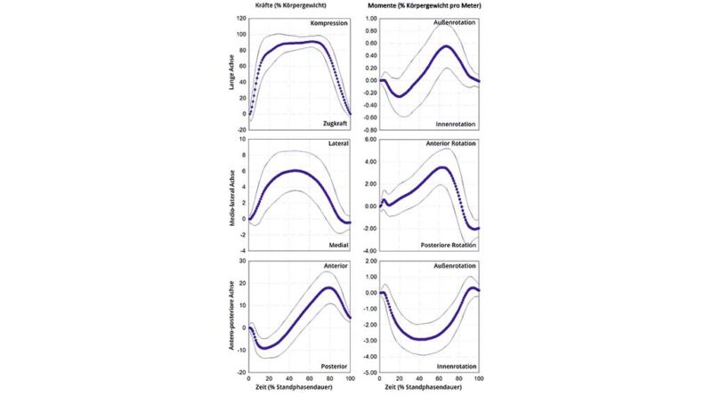
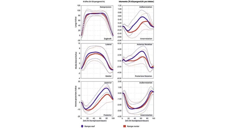
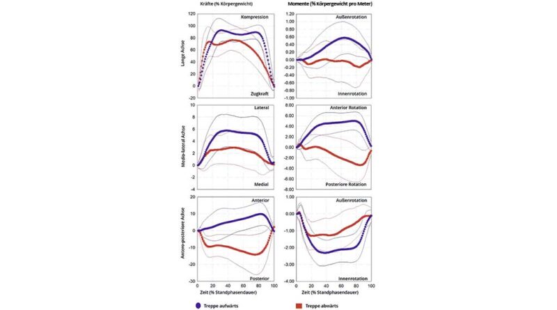
Tabelle 1 Mittelwert und Standardabweichung der spatiotemporalen Variablen, einschließlich der Kadenz, der Dauer des Gangzyklus (GC) und der Stützphase mit den modernen Komponenten während der täglichen Aktivitäten.
| Gehen | Rampenaufstieg | Rampenabstieg | Treppenaufstieg | Treppenabstieg | ||||||
|---|---|---|---|---|---|---|---|---|---|---|
| Kadenz (Schritte/min) | 47 ± 6 | L | 45 ± 4 | L | 45 ± 6 | L | 38 ± 6 | L | 36 ± 7 | H |
| Gangzyklus (s) | 1,34 ± 0,22 | L | 1,34 ± 0,18 | L | 1,37 ± 0,21 | L | 1,55 ± 0,24 | L | 1,72 ± 0,60 | H |
| Unterstützung (%GC) | 63 ± 4 | L | 64 ± 6 | L | 63 ± 6 | L | 52 ± 6 | L | 52 ± 11 | H |
%SUP: Prozentsatz der Stützphase, %BW: Prozentsatz Körpergewicht, H: Hoher PV, L: Niedriger PV.
Tabelle 2 Belastungsgrenzen der Größenordnung von Kräften (F) und Momenten (M) auf die Längsachse (LG), die anterior-posteriore Achse (AP) und die mediolaterale Achse (ML) des osseointegrierten Implantats, die von den modernen Komponenten bei täglichen Aktivitäten ausgeübt werden.
| Gehen | Rampenaufstieg | Rampenabstieg | Treppenaufstieg | Treppenabstieg | ||||||
|---|---|---|---|---|---|---|---|---|---|---|
| Minimum | ||||||||||
| FLG (%BW) | –3,81 ± 4,35 | H | –4,12 ± 4,39 | H | –2,01 ± 5,46 | H | –3,40 ± 4,77 | H | –2,39 ± 5,98 | H |
| FAP (%BW) | –11,35 ± 4,19 | H | –10,92 ± 4,05 | H | –13,77 ± 5,80 | H | –3,74 ± 5,37 | H | –19,04 ± 8,53 | H |
| FML (%BW) | –1,20 ± 0,80 | H | –1,20 ± 0,82 | H | –1,26 ± 1,10 | H | –0,69 ± 0,70 | H | –1,58 ± 1,68 | H |
| MLG (%BWm) | –0,441 ± 0,283 | H | –0,396 ± 0,239 | H | –0,548 ± 0,278 | H | –0,205 ± 0,182 | H | –0,559 ± 0,410 | H |
| MAP (%BWm) | –3,438 ± 0,982 | H | –3,168 ± 0,832 | H | –3,150 ± 1,065 | H | –2,780 ± 0,802 | H | –2,040 ± 0,811 | H |
| MML (%BWm) | –2,469 ± 1,012 | H | –2,922 ± 0,788 | H | –2,833 ± 1,254 | H | –0,346 ± 0,410 | H | –4,315 ± 2,333 | H |
| Maximum | ||||||||||
| FLG (%BW) | 101,97 ± 6,76 | L | 100,55 ± 6,88 | L | 105,43 ± 11,28 | L | 108,27 ± 9,56 | L | 95,48 ± 18,31 | L |
| FAP (%BW) | 19,74 ± 7,04 | H | 22,43 ± 6,00 | H | 15,72 ± 8,31 | H | 11,05 ± 6,33 | H | 3,60 ± 2,09 | H |
| FML (%BW) | 7,02 ± 2,72 | H | 7,62 ± 2,73 | H | 6,97 ± 3,06 | H | 6,96 ± 3,07 | H | 4,37 ± 2,35 | H |
| MLG (%BWm) | 0,734 ± 0,331 | H | 0,730 ± 0,358 | H | 0,603 ± 0,423 | H | 0,744 ± 0,387 | H | 0,426 ± 0,375 | H |
| MAP (%BWm) | 0,787 ± 0,523 | H | 0,821 ± 0,575 | H | 0,653 ± 0,492 | H | 0,486 ± 0,383 | H | 0,675 ± 0,534 | H |
| MML (%BWm) | 4,131 ± 1,208 | H | 4,027 ± 1,328 | H | 2,671 ± 1,570 | H | 5,701 ± 1,808 | H | 1,910 ± 1,502 | H |
%BW: Prozentsatz Körpergewicht, H: Hoher PV, L: Niedriger PV.
Tabelle 3 Mittelwert und Standardabweichung des Beginns und der Größenordnung der Belastungsextrema von Kräften (F) und Momenten (M) auf die Längsachse (LG), die anterior-posteriore Achse (AP) und die mediolaterale Achse (ML) des osseointegrierten Implantats, die von den modernen Komponenten bei täglichen Aktivitäten ausgeübt werden.
| Gehen | Rampenaufstieg | Rampenabstieg | Treppenaufstieg | Treppenabstieg | ||||||
|---|---|---|---|---|---|---|---|---|---|---|
| Beginn | ||||||||||
| FLG1 (%SUP) | 37,45 ± 18,32 | H | 37,85 ± 20,24 | H | 33,42 ± 15,48 | H | 36,60 ± 18,58 | H | 32,79 ± 21,46 | H |
| FAP1 (%SUP) | 18,03 ± 9,64 | H | 14,49 ± 6,51 | H | 22,54 ± 11,82 | H | 8,60 ± 9,76 | H | 53,06 ± 29,38 | H |
| FAP2 (%SUP) | 79,61 ± 6,20 | L | 79,87 ± 6,32 | L | 83,45 ± 8,17 | L | 81,66 ± 11,68 | L | – | - |
| FML1 (%SUP) | 43,31 ± 15,33 | H | 42,75 ± 16,87 | H | 45,39 ± 18,06 | H | 42,20 ± 19,95 | H | 39,84 ± 21,58 | H |
| MLG1 (%SUP) | 22,65 ± 13,20 | H | 19,21 ± 11,03 | H | 30,56 ± 15,84 | H | 16,35 ± 16,52 | H | 56,23 ± 31,08 | H |
| MLG2 (%SUP) | 67,07 ± 10,83 | L | 66,29 ± 11,19 | L | 72,96 ± 18,64 | H | 64,28 ± 18,73 | H | – | – |
| MAP1 (%SUP) | 36,11 ± 13,74 | H | 33,18 ± 13,27 | H | 41,96 ± 16,58 | H | 45,26 ± 19,79 | H | 36,21 ± 20,26 | H |
| MML1 (%SUP) | 9,00 ± 8,20 | H | 10,67 ± 8,75 | H | 59,95 ± 17,36 | H | 65,75 ± 19,79 | H | 83,49 ± 15,31 | L |
| MML2 (%SUP) | 65,79 ± 8,07 | L | 65,37 ± 8,02 | L | 89,03 ± 6,07 | L | – | – | – | – |
| MML3 (%SUP) | 89,14 ± 6,39 | L | 88,82 ± 6,27 | L | – | – | – | – | – | – |
| Größenordnung | ||||||||||
| FLG1 (%BW) | 101,97 ± 6,76 | L | 100,55 ± 6,88 | L | 105,33 ± 11,40 | L | 108,24 ± 9,57 | L | 95,48 ± 18,31 | L |
| FAP1 (%BW) | –11,35 ± 4,19 | H | –10,92 ± 4,05 | H | –13,73 ± 5,77 | H | –3,25 ± 5,60 | H | –19,04 ± 8,53 | H |
| FAP2 (%BW) | 19,74 ± 7,04 | H | 22,43 ± 6,00 | H | 15,50 ± 8,74 | H | 11,01 ± 6,37 | H | – | – |
| FML1 (%BW) | 7,02 ± 2,72 | H | 7,61 ± 2,74 | H | 6,97 ± 3,06 | H | 6,95 ± 3,09 | H | 4,28 ± 2,46 | H |
| MLG1 (%BWm) | –0,431 ± 0,291 | H | –0,384 ± 0,247 | H | –0,541 ± 0,283 | H | –0,185 ± 0,192 | H | –0,559 ± 0,410 | H |
| MLG2 (%BWm) | 0,734 ± 0,331 | H | 0,730 ± 0,358 | H | 0,598 ± 0,430 | H | 0,744 ± 0,388 | H | – | – |
| MAP1 (%BWm) | –3,438 ± 0,982 | H | –3,168 ± 0,832 | H | –3,150 ± 1,065 | H | –2,779 ± 0,802 | H | –2,036 ± 0,814 | H |
| MML1 (%BWm) | –0,751 ± 0,683 | H | –0,865 ± 0,733 | H | 2,287 ± 1,974 | H | 5,696 ± 1,808 | H | –4,307 ± 2,347 | H |
| MML2 (%BWm) | 4,096 ± 1,254 | H | 3,980 ± 1,381 | H | –2,813 ± 1,234 | H | – | – | – | – |
| MML3 (%BWm) | –2,466 ± 1,013 | H | –2,920 ± 0,790 | H | – | – | – | – | – | – |
%SUP: Prozentsatz der Stützphase, %BW: Prozentsatz Körpergewicht, H: Hoher PV, L: Niedriger PV.
Quellenverzeichnis
- Gips oder Orthese bei distalen Radiusfrakturen? — 8. April 2026
- Die orthopädietechnische Versorgung mit einer dynamischen Fingerstreckorthese als eigenständige Therapie bei der Dupuytren’schen Kontraktur — 26. März 2026
- Vergleichende Prüfung konventioneller und additiv gefertigter Prothesenschäfte in Anlehnung an DIN EN ISO 10328:2016 — 10. März 2026
- Samuelsson KA et al. Effects of lower limb prosthesis on activity, participation, and quality of life: a systematic review. Prosthetics and Orthotics International, 2012; 36 (2): 145–158. https://doi.org/10.1177/0309364611432794
- Meulenbelt HE et al. Skin problems in lower limb amputees: a systematic review. Disability and Rehabilitation, 2006; 28 (10): 603–608. https://doi.org/10.1080/09638280500277032
- Brånemark R et al. Osseointegration in skeletal reconstruction and rehabilitation: a review. Journal of Rehabilitation Research and Development, 2001; 38 (2): 175–181
- Pitkin M. Design features of implants for direct skeletal attachment of limb prostheses. Journal of Biomedical Materials Research Part A, 2013; 101 (11): 3339–3348. https://doi.org/10.1002/jbm.a.34606
- Atallah R et al. Safety, prosthesis wearing time and health-related quality of life of lower extremity bone-anchored prostheses using a press-fit titanium osseointegration implant: a prospective one-year follow-up cohort study. PLoS One, 2020; 15 (3): e0230027. https://doi.org/10.1371/journal.pone.0230027
- Hagberg K, Branemark R. One hundred patients treated with osseointegrated transfemoral amputation prostheses: rehabilitation perspective. Journal of Rehabilitation Research and Development, 2009; 46 (3): 331–344
- Hebert JS, Rehani M, Stiegelmar R. Osseointegration for Lower-Limb Amputation: A Systematic Review of Clinical Outcomes. JBJS Reviews, 2017; 5 (10): e10. https://doi.org/10.2106/JBJS.RVW.17.00037
- Hoyt BW, Walsh SA, Forsberg JA. Osseointegrated prostheses for the rehabilitation of amputees (OPRA): results and clinical perspective. Expert Review of Medical Devices, 2020; 17 (1): 17–25. https://doi.org/10.1080/17434440.2020.1704623
- Leijendekkers RA et al. Comparison of bone-anchored prostheses and socket prostheses for patients with a lower extremity amputation: a systematic review. Disability and Rehabilitation, 2017; 39 (11): 1045–1058. https://doi.org/10.1080/09638288.2016.1186752
- van Eck CF, McGough RL. Clinical outcome of osseointegrated prostheses for lower extremity amputations: a systematic review of the literature. Current Orthopaedic Practice, 2015; 26 (4): 349–357. https://doi.org/10.1097/bco.0000000000000248
- Atallah R et al. Safety, prosthesis wearing time and health-related quality of life of lower extremity bone-anchored prostheses using a press-fit titanium osseointegration implant: a prospective one-year follow-up cohort study. PLoS One, 2020; 15 (3): e0230027. https://doi.org/10.1371/journal.pone.0230027
- Hoyt BW, Walsh SA, Forsberg JA. Osseointegrated prostheses for the rehabilitation of amputees (OPRA): results and clinical perspective. Expert Review of Medical Devices, 2020; 17 (1): 17–25. https://doi.org/10.1080/17434440.2020.1704623
- van Eck CF, McGough RL. Clinical outcome of osseointegrated prostheses for lower extremity amputations: a systematic review of the literature. Current Orthopaedic Practice, 2015; 26 (4): 349–357. https://doi.org/10.1097/bco.0000000000000248
- Atallah R et al. Complications of bone-anchored prostheses for individuals with an extremity amputation: a systematic review. PLoS One, 2018; 13 (8): e0201821. https://doi.org/10.1371/journal.pone.0201821
- Kunutsor SK, Gillatt D, Blom AW. Systematic review of the safety and efficacy of osseointegration prosthesis after limb amputation. British Journal of Surgery, 2018; 105 (13): 1731–1741. https://doi.org/10.1002/bjs.11005
- Frossard L et al. Cost comparison of socket-suspended and bone-anchored Transfemoral prostheses. JPO Journal of Prosthetics and Orthotics, 2017; 29 (4): 150–160. https://doi.org/10.1097/jpo.0000000000000142
- Frossard L. Development of a government continuous quality improvement procedure for assessing the provision of bone anchored limb prosthesis: a process re-design descriptive study. Canadian Prosthetics and Orthotics Journal, 2018; 1 (2): 1–14
- Frossard LA et al. Cost-effectiveness of bone-anchored prostheses using osseointegrated fixation: myth or reality? Prosthetics and Orthotics International, 2018; 42 (3): 318–327. https://doi.org/10.1177/0309364617740239
- Frossard L. Cost-Effectiveness of Transtibial Bone-Anchored Prostheses Using Osseointegrated Fixation: From Challenges to Preliminary Data. JPO Journal of Prosthetics and Orthotics, 2021; 33: 184–195. https://doi.org/10.1097/jpo.0000000000000372
- Helgason B et al. Risk of failure during gait for direct skeletal attachment of a femoral prosthesis: a finite element study. Medical Engineering and Physics, 2009; 31 (5): 595–600. https://doi.org/10.1016/j.medengphy.2008.11.015
- Lee WC et al. FE stress analysis of the interface between the bone and an osseointegrated implant for amputees – Implications to refine the rehabilitation program. Clinical Biomechanics (Bristol, Avon), 2008; 23 (10): 1243–1250. https://doi.org/10.1016/j.clinbiomech.2008.06.012
- Newcombe L et al. Effect of amputation level on the stress transferred to the femur by an artificial limb directly attached to the bone. Medical Engineering and Physics, 2013; 35 (12): 1744–1753. https://doi.org/10.1016/j.medengphy.2013.07.007
- Stenlund P et al. Effect of load on the bone around bone-anchored amputation prostheses. Journal of Orthopaedic Research, 2017; 35 (5): 1113–1122. https://doi.org/10.1002/jor.23352
- Stephenson P, Seedhom BB. Estimation of forces at the interface between an artificial limb and an implant directly fixed into the femur in above-knee amputees. Journal of Orthopaedic Science, 2002; 7 (3): 192–297
- Thesleff A et al. Biomechanical characterisation of bone-anchored implant Systems for Amputation Limb Prostheses: a systematic review. Annals of Biomedical Engineering, 2018; 46: 377–391. https://doi.org/10.1007/s10439-017‑1976‑4
- Morgenroth DC. Prescribing physician perspective on microprocessor-controlled prosthetic knees. JPO Journal of Prosthetics and Orthotics, 2013; 25 (4S): P53–P55. https://doi.org/10.1097/JPO.0b013e3182a88d02
- Lee W et al. Evidence-based rehabilitation of amputees using osseointegrated prostheses: applications of finite element modelling. In: Proceedings of the XIIth world congress of the international society of prosthetics and orthotic. Vancouver, Canada, 2007
- Lee W et al. Magnitude and variability of loading on the osseointegrated implant of transfemoral amputees during walking. Medical Engineering and Physics, 2008; 30 (7): 825–833. https://doi.org/10.1016/j.medengphy.2007.09.003
- Frossard L et al. Load applied on a bone-anchored transfemoral prosthesis: characterisation of prosthetic components – A case study. Journal of Rehabilitation Research and Development, 2013; 50 (5): 619–634. https://doi.org/10.1682/JRRD.2012.04.0062
- Juhnke D et al. Fifteen years of experience with integral-leg-prosthesis: cohort study of artificial limb attachment system. Journal of Rehabilitation Research and Development, 2015; 52 (4): 407–420. https://doi.org/10.1682/jrrd.2014.11.0280
- Kaufman KR, Frittoli S, Frigo CA. Gait asymmetry of transfemoral amputees using mechanical and microprocessor-controlled prosthetic knees. Clinical Biomechanics, 2012; 27 (5): 460–465. https://doi.org/10.1016/j.clinbiomech.2011.11.011
- Struchkov V, Buckley JG. Biomechanics of ramp descent in unilateral trans-tibial amputees: comparison of a microprocessor controlled foot with conventional ankle-foot mechanisms. Clinical Biomechanics, 2016; 32: 164–170. https://doi.org/10.1016/j.clinbiomech.2015.11.015
- OPRA. Implant System Instructions for Use, 2016. https://www.accessdata.fda.gov/cdrh_docs/pdf8/H080004D.pdf (Zugriff am 07.07.2024)
- Frossard L et al. Development and preliminary testing of a device for the direct measurement of forces and moments in the prosthetic limb of transfemoral amputees during activities of daily living. JPO Journal of Prosthetics and Orthotics, 2003; 15 (4): 135–142
- Frossard L et al. Monitoring of the load regime applied on the osseointegrated fixation of a trans-femoral amputee: a tool for evidence-based practice. Prosthetics and Orthotics International, 2008; 32 (1): 68–78. https://doi.org/10.1080/03093640701676319
- Frossard L et al. Categorization of activities of daily living of lower limb amputees during short-term use of a portable kinetic recording system: a preliminary study. JPO Journal of Prosthetics and Orthotics, 2011; 23 (1): 2–11. https://doi.org/10.1097/JPO.0b013e318207914c
- Robinson DL et al. Load response of an osseointegrated implant used in the treatment of unilateral transfemoral amputation: an early implant loosening case study. Clinical Biomechanics, 2020; 73: 201–212. https://doi.org/10.1016/j.clinbiomech.2020.01.017
- Frossard L et al. Load applied on a bone-anchored transfemoral prosthesis: characterisation of prosthetic components – A case study. Journal of Rehabilitation Research and Development, 2013; 50 (5): 619–634. https://doi.org/10.1682/JRRD.2012.04.0062
- Campbell JH, Stevens PM, Wurdeman SR. OASIS 1: retrospective analysis of four different microprocessor knee types. Journal of Rehabilitation and Assistive Technology Engineering, 2020; 7: 2055668320968476. https://doi.org/10.1177/2055668320968476
- Highsmith MJ et al. Safety, energy efficiency, and cost efficacy of the C‑leg for transfemoral amputees: a review of the literature. Prosthetics and Orthotics International, 2010; 34 (4): 362–377. https://doi.org/10.3109/03093646.2010.520054
- Kahle JT, Highsmith MJ, Hubbard SL. Comparison of nonmicroprocessor knee mechanism versus C‑leg on prosthesis evaluation questionnaire, stumbles, falls, walking tests, stair descent, and knee preference. Journal of Rehabilitation Research and Development, 2008; 45 (1): 1–14
- Orendurff M et al. Gait efficiency using the C‑leg. Journal of Rehabilitation Research and Development, 2006; 43 (2): 239–246
- Sawers AB, Hafner BJ. Outcomes associated with the use of microprocessor-controlled prosthetic knees among individuals with unilateral transfemoral limb loss: a systematic review. Journal of Rehabilitation Research and Development, 2013; 50 (3): 273–314
- Pitkin M, Frossard L. Loading effect of prosthetic Feet’s anthropomorphicity on transtibial osseointegrated implant. Military Medicine, 2021; 186 (1): 681–687. https://doi.org/10.1093/milmed/usaa461
- Pitkin M, Frossard L. Loading effect of prosthetic Feet’s anthropomorphicity on transtibial osseointegrated implant. Military Medicine, 2021; 186 (1): 681–687. https://doi.org/10.1093/milmed/usaa461
- Thesleff A et al. Biomechanical characterisation of bone-anchored implant Systems for Amputation Limb Prostheses: a systematic review. Annals of Biomedical Engineering, 2018; 46: 377–391. https://doi.org/10.1007/s10439-017‑1976‑4
- Dumas R, Cheze L, Frossard L. Loading applied on prosthetic knee of transfemoral amputee: comparison of inverse dynamics and direct measurements. Gait and Posture, 2009; 30 (4): 560–562. https://doi.org/10.1016/j.gaitpost.2009.07.126
- Dumas R, Branemark R, Frossard L. Gait analysis of transfemoral amputees: errors in inverse dynamics are substantial and depend on prosthetic design. IEEE Transactions on Neural Systems and Rehabilitation Engineering, 2017; 25 (6): 679–685. https://doi.org/10.1109/TNSRE.2016.2601378
- Frossard L, Cheze L, Dumas R. Dynamic input to determine hip joint moments, power and work on the prosthetic limb of transfemoral amputees: ground reaction vs knee reaction. Prosthetics and Orthotics International, 2011; 35 (2): 140–149. https://doi.org/10.1177/0309364611409002
- Harandi VJ et al. Individual muscle contributions to hip joint-contact forces during walking in unilateral transfemoral amputees with osseointegrated prostheses. Computer Methods in Biomechanics and Biomedical Engineering, 2020; 1–11. https://doi.org/10.1080/10255842.2020.1786686
- Niswander W, Wang W, Baumann AP. Characterizing loads at transfemoral osseointegrated implants. Medical Engineering and Physics, 2020; 84: 103–114. https://doi.org/10.1016/j.medengphy.2020.08.005
- Lee W et al. Evidence-based rehabilitation of amputees using osseointegrated prostheses: applications of finite element modelling. In: Proceedings of the XIIth world congress of the international society of prosthetics and orthotic. Vancouver, Canada, 2007
- Lee W et al. Magnitude and variability of loading on the osseointegrated implant of transfemoral amputees during walking. Medical Engineering and Physics, 2008; 30 (7): 825–833. https://doi.org/10.1016/j.medengphy.2007.09.003
- Frossard L. Loading characteristics data applied on osseointegrated implant by transfemoral bone-anchored prostheses fitted with basic components during daily activities. Data in Brief, 2019; 26: 104492. https://doi.org/10.1016/j.dib.2019.104492
- Frossard L et al. Load applied on a bone-anchored transfemoral prosthesis: characterisation of prosthetic components – A case study. Journal of Rehabilitation Research and Development, 2013; 50 (5): 619–634. https://doi.org/10.1682/JRRD.2012.04.0062
- Frossard L et al. Load applied on a bone-anchored transfemoral prosthesis: characterisation of prosthetic components – A case study. Journal of Rehabilitation Research and Development, 2013; 50 (5): 619–634. https://doi.org/10.1682/JRRD.2012.04.0062
- Frossard L. Loading characteristics data applied on osseointegrated implant by transfemoral bone-anchored prostheses fitted with basic components during daily activities. Data in Brief, 2019; 26: 104492. https://doi.org/10.1016/j.dib.2019.104492
- Frossard L, Leech B, Pitkin M. Automated characterization of anthropomorphicity of prosthetic feet fitted to bone-anchored transtibial prosthesis. IEEE Transactions on Biomedical Engineering, 2019; 66 (12): 3402–3410. https://doi.org/10.1109/TBME.2019.2904713
- Niswander W, Wang W, Baumann AP. Characterizing loads at transfemoral osseointegrated implants. Medical Engineering and Physics, 2020; 84: 103–114. https://doi.org/10.1016/j.medengphy.2020.08.005
- Frossard L. Loading characteristics data applied on osseointegrated implant by transfemoral bone-anchored prostheses fitted with basic components during daily activities. Data in Brief, 2019; 26: 104492. https://doi.org/10.1016/j.dib.2019.104492
- Lee W et al. Evidence-based rehabilitation of amputees using osseointegrated prostheses: applications of finite element modelling. In: Proceedings of the XIIth world congress of the international society of prosthetics and orthotic. Vancouver, Canada, 2007
- Lee W et al. Magnitude and variability of loading on the osseointegrated implant of transfemoral amputees during walking. Medical Engineering and Physics, 2008; 30 (7): 825–833. https://doi.org/10.1016/j.medengphy.2007.09.003
- Frossard L et al. Development and preliminary testing of a device for the direct measurement of forces and moments in the prosthetic limb of transfemoral amputees during activities of daily living. JPO Journal of Prosthetics and Orthotics, 2003; 15 (4): 135–142
- Frossard L et al. Functional outcome of Transfemoral amputees fitted with an Osseointegrated fixation: temporal gait characteristics. JPO Journal of Prosthetics and Orthotics, 2010; 22 (1): 11–20. https://doi.org/10.1097/JPO.0b013e3181ccc53d
- Atallah R et al. Safety, prosthesis wearing time and health-related quality of life of lower extremity bone-anchored prostheses using a press-fit titanium osseointegration implant: a prospective one-year follow-up cohort study. PLoS One, 2020; 15 (3): e0230027. https://doi.org/10.1371/journal.pone.0230027
- Frossard L, Leech B, Pitkin M. Automated characterization of anthropomorphicity of prosthetic feet fitted to bone-anchored transtibial prosthesis. IEEE Transactions on Biomedical Engineering, 2019; 66 (12): 3402–3410. https://doi.org/10.1109/TBME.2019.2904713
- Frossard L, Leech B, Pitkin M. Loading applied on osseointegrated implant by transtibial bone-anchored prostheses during daily activities: preliminary characterization of prosthetic feet. JPO Journal of Prosthetics and Orthotics, 2020; 32 (4): 258–271. https://doi.org/10.1097/jpo.0000000000000280
- Koehler SR, Dhaher YY, Hansen AH. Cross-validation of a portable, six-degree-of-freedom load cell for use in lower-limb prosthetics research. Journal of Biomechanics, 2014; 47 (6): 1542–1547. https://doi.org/10.1016/j.jbiomech.2014.01.048
- Blumentritt S. A new biomechanical method for determination of static prosthetic alignment. Prosthetics and Orthotics International, 1997; 21 (2): 107–113. https://doi.org/10.3109/03093649709164538
- Blumentritt S. Function of prosthesis components in lower limb amputees with bone-anchored percutaneous implants-Biomechanical aspects. Unfallchirurg, 2017; 1–10. https://doi.org/10.1007/s00113-017‑0334‑1
- Frossard L. Loading characteristics data applied on osseointegrated implant by transfemoral bone-anchored prostheses fitted with basic components during daily activities. Data in Brief, 2019; 26: 104492. https://doi.org/10.1016/j.dib.2019.104492
- Schmalz T et al. Effects of adaptation to a functionally new prosthetic lower-limb component: results of biomechanical tests immediately after fitting and after 3 months of use. JPO Journal of Prosthetics and Orthotics, 2014; 26 (3): 134–143. https://doi.org/10.1097/jpo.0000000000000028
- Lee W et al. Evidence-based rehabilitation of amputees using osseointegrated prostheses: applications of finite element modelling. In: Proceedings of the XIIth world congress of the international society of prosthetics and orthotic. Vancouver, Canada, 2007
- Lee W et al. Magnitude and variability of loading on the osseointegrated implant of transfemoral amputees during walking. Medical Engineering and Physics, 2008; 30 (7): 825–833. https://doi.org/10.1016/j.medengphy.2007.09.003
- Frossard L et al. Load applied on a bone-anchored transfemoral prosthesis: characterisation of prosthetic components – A case study. Journal of Rehabilitation Research and Development, 2013; 50 (5): 619–634. https://doi.org/10.1682/JRRD.2012.04.0062
- Frossard L, Leech B, Pitkin M. Automated characterization of anthropomorphicity of prosthetic feet fitted to bone-anchored transtibial prosthesis. IEEE Transactions on Biomedical Engineering, 2019; 66 (12): 3402–3410. https://doi.org/10.1109/TBME.2019.2904713
- Frossard L, Leech B, Pitkin M. Loading applied on osseointegrated implant by transtibial bone-anchored prostheses during daily activities: preliminary characterization of prosthetic feet. JPO Journal of Prosthetics and Orthotics, 2020; 32 (4): 258–271. https://doi.org/10.1097/jpo.0000000000000280
- Koehler SR, Dhaher YY, Hansen AH. Cross-validation of a portable, six-degree-of-freedom load cell for use in lower-limb prosthetics research. Journal of Biomechanics, 2014; 47 (6): 1542–1547. https://doi.org/10.1016/j.jbiomech.2014.01.048
- Reid SM et al. Knee biomechanics of alternate stair ambulation patterns. Medicine & Science in Sports & Exercise, 2007; 39 (11): 2005–2011. https://doi.org/10.1249/mss.0b013e31814538c8
- Lee W et al. Evidence-based rehabilitation of amputees using osseointegrated prostheses: applications of finite element modelling. In: Proceedings of the XIIth world congress of the international society of prosthetics and orthotic. Vancouver, Canada, 2007
- Lee W et al. Magnitude and variability of loading on the osseointegrated implant of transfemoral amputees during walking. Medical Engineering and Physics, 2008; 30 (7): 825–833. https://doi.org/10.1016/j.medengphy.2007.09.003
- Frossard L et al. Load applied on a bone-anchored transfemoral prosthesis: characterisation of prosthetic components – A case study. Journal of Rehabilitation Research and Development, 2013; 50 (5): 619–634. https://doi.org/10.1682/JRRD.2012.04.0062
- Frossard L et al. Development and preliminary testing of a device for the direct measurement of forces and moments in the prosthetic limb of transfemoral amputees during activities of daily living. JPO Journal of Prosthetics and Orthotics, 2003; 15 (4): 135–142
- Frossard L et al. Functional outcome of Transfemoral amputees fitted with an Osseointegrated fixation: temporal gait characteristics. JPO Journal of Prosthetics and Orthotics, 2010; 22 (1): 11–20. https://doi.org/10.1097/JPO.0b013e3181ccc53d
- Frossard L, Leech B, Pitkin M. Automated characterization of anthropomorphicity of prosthetic feet fitted to bone-anchored transtibial prosthesis. IEEE Transactions on Biomedical Engineering, 2019; 66 (12): 3402–3410. https://doi.org/10.1109/TBME.2019.2904713
- Frossard L et al. Functional outcome of Transfemoral amputees fitted with an Osseointegrated fixation: temporal gait characteristics. JPO Journal of Prosthetics and Orthotics, 2010; 22 (1): 11–20. https://doi.org/10.1097/JPO.0b013e3181ccc53d
- Reid SM et al. Knee biomechanics of alternate stair ambulation patterns. Medicine & Science in Sports & Exercise, 2007; 39 (11): 2005–2011. https://doi.org/10.1249/mss.0b013e31814538c8
- Lee W et al. Evidence-based rehabilitation of amputees using osseointegrated prostheses: applications of finite element modelling. In: Proceedings of the XIIth world congress of the international society of prosthetics and orthotic. Vancouver, Canada, 2007
- Lee W et al. Magnitude and variability of loading on the osseointegrated implant of transfemoral amputees during walking. Medical Engineering and Physics, 2008; 30 (7): 825–833. https://doi.org/10.1016/j.medengphy.2007.09.003
- Frossard L et al. Load applied on a bone-anchored transfemoral prosthesis: characterisation of prosthetic components – A case study. Journal of Rehabilitation Research and Development, 2013; 50 (5): 619–634. https://doi.org/10.1682/JRRD.2012.04.0062
- Frossard L et al. Development and preliminary testing of a device for the direct measurement of forces and moments in the prosthetic limb of transfemoral amputees during activities of daily living. JPO Journal of Prosthetics and Orthotics, 2003; 15 (4): 135–142
- Frossard L et al. Load-relief of walking aids on osseointegrated fixation: instrument for evidence-based practice. IEEE Transactions on Neural Systems and Rehabilitation Engineering, 2009; 17 (1): 9–14. https://doi.org/10.1109/TNSRE.2008.2010478
- Frossard L. Loading characteristics data applied on osseointegrated implant by transfemoral bone-anchored prostheses fitted with basic components during daily activities. Data in Brief, 2019; 26: 104492. https://doi.org/10.1016/j.dib.2019.104492
- Lee W et al. Evidence-based rehabilitation of amputees using osseointegrated prostheses: applications of finite element modelling. In: Proceedings of the XIIth world congress of the international society of prosthetics and orthotic. Vancouver, Canada, 2007
- Lee W et al. Magnitude and variability of loading on the osseointegrated implant of transfemoral amputees during walking. Medical Engineering and Physics, 2008; 30 (7): 825–833. https://doi.org/10.1016/j.medengphy.2007.09.003
- Frossard L et al. Load applied on a bone-anchored transfemoral prosthesis: characterisation of prosthetic components – A case study. Journal of Rehabilitation Research and Development, 2013; 50 (5): 619–634. https://doi.org/10.1682/JRRD.2012.04.0062
- Frossard L. Loading characteristics data applied on osseointegrated implant by transfemoral bone-anchored prostheses fitted with basic components during daily activities. Data in Brief, 2019; 26: 104492. https://doi.org/10.1016/j.dib.2019.104492
- Frossard L et al. Functional outcome of Transfemoral amputees fitted with an Osseointegrated fixation: temporal gait characteristics. JPO Journal of Prosthetics and Orthotics, 2010; 22 (1): 11–20. https://doi.org/10.1097/JPO.0b013e3181ccc53d
- Frossard L. Loading characteristics data applied on osseointegrated implant by transfemoral bone-anchored prostheses fitted with basic components during daily activities. Data in Brief, 2019; 26: 104492. https://doi.org/10.1016/j.dib.2019.104492
- Lee W et al. Evidence-based rehabilitation of amputees using osseointegrated prostheses: applications of finite element modelling. In: Proceedings of the XIIth world congress of the international society of prosthetics and orthotic. Vancouver, Canada, 2007
- Lee W et al. Magnitude and variability of loading on the osseointegrated implant of transfemoral amputees during walking. Medical Engineering and Physics, 2008; 30 (7): 825–833. https://doi.org/10.1016/j.medengphy.2007.09.003
- Frossard L et al. Monitoring of the load regime applied on the osseointegrated fixation of a trans-femoral amputee: a tool for evidence-based practice. Prosthetics and Orthotics International, 2008; 32 (1): 68–78. https://doi.org/10.1080/03093640701676319
- Dumas R, Cheze L, Frossard L. Loading applied on prosthetic knee of transfemoral amputee: comparison of inverse dynamics and direct measurements. Gait and Posture, 2009; 30 (4): 560–562. https://doi.org/10.1016/j.gaitpost.2009.07.126
- Dumas R, Branemark R, Frossard L. Gait analysis of transfemoral amputees: errors in inverse dynamics are substantial and depend on prosthetic design. IEEE Transactions on Neural Systems and Rehabilitation Engineering, 2017; 25 (6): 679–685. https://doi.org/10.1109/TNSRE.2016.2601378
- Frossard L, Cheze L, Dumas R. Dynamic input to determine hip joint moments, power and work on the prosthetic limb of transfemoral amputees: ground reaction vs knee reaction. Prosthetics and Orthotics International, 2011; 35 (2): 140–149. https://doi.org/10.1177/0309364611409002
- Frossard L et al. Functional outcome of Transfemoral amputees fitted with an Osseointegrated fixation: temporal gait characteristics. JPO Journal of Prosthetics and Orthotics, 2010; 22 (1): 11–20. https://doi.org/10.1097/JPO.0b013e3181ccc53d
- Frossard L et al. Apparatus for monitoring load bearing rehabilitation exercises of a transfemoral amputee fitted with an osseointegrated fixation: a proof-of-concept study. Gait and Posture, 2010; 31 (2): 223–228. https://doi.org/10.1016/j.gaitpost.2009.10.010
- Dumas R, Cheze L, Frossard L. Loading applied on prosthetic knee of transfemoral amputee: comparison of inverse dynamics and direct measurements. Gait and Posture, 2009; 30 (4): 560–562. https://doi.org/10.1016/j.gaitpost.2009.07.126
- Dumas R, Branemark R, Frossard L. Gait analysis of transfemoral amputees: errors in inverse dynamics are substantial and depend on prosthetic design. IEEE Transactions on Neural Systems and Rehabilitation Engineering, 2017; 25 (6): 679–685. https://doi.org/10.1109/TNSRE.2016.2601378
- Frossard L, Cheze L, Dumas R. Dynamic input to determine hip joint moments, power and work on the prosthetic limb of transfemoral amputees: ground reaction vs knee reaction. Prosthetics and Orthotics International, 2011; 35 (2): 140–149. https://doi.org/10.1177/0309364611409002
- Lee W et al. Evidence-based rehabilitation of amputees using osseointegrated prostheses: applications of finite element modelling. In: Proceedings of the XIIth world congress of the international society of prosthetics and orthotic. Vancouver, Canada, 2007
- Lee W et al. Magnitude and variability of loading on the osseointegrated implant of transfemoral amputees during walking. Medical Engineering and Physics, 2008; 30 (7): 825–833. https://doi.org/10.1016/j.medengphy.2007.09.003
- Frossard L, Leech B, Pitkin M. Automated characterization of anthropomorphicity of prosthetic feet fitted to bone-anchored transtibial prosthesis. IEEE Transactions on Biomedical Engineering, 2019; 66 (12): 3402–3410. https://doi.org/10.1109/TBME.2019.2904713
- Frossard L et al. Functional outcome of Transfemoral amputees fitted with an Osseointegrated fixation: temporal gait characteristics. JPO Journal of Prosthetics and Orthotics, 2010; 22 (1): 11–20. https://doi.org/10.1097/JPO.0b013e3181ccc53d
- Frossard L. Cost-Effectiveness of Transtibial Bone-Anchored Prostheses Using Osseointegrated Fixation: From Challenges to Preliminary Data. JPO Journal of Prosthetics and Orthotics, 2021; 33: 184–195. https://doi.org/10.1097/jpo.0000000000000372
- Frossard L. Loading characteristics data applied on osseointegrated implant by transfemoral bone-anchored prostheses fitted with basic components during daily activities. Data in Brief, 2019; 26: 104492. https://doi.org/10.1016/j.dib.2019.104492
- Frossard L et al. Functional outcome of Transfemoral amputees fitted with an Osseointegrated fixation: temporal gait characteristics. JPO Journal of Prosthetics and Orthotics, 2010; 22 (1): 11–20. https://doi.org/10.1097/JPO.0b013e3181ccc53d
- Frossard L et al. Apparatus for monitoring load bearing rehabilitation exercises of a transfemoral amputee fitted with an osseointegrated fixation: a proof-of-concept study. Gait and Posture, 2010; 31 (2): 223–228. https://doi.org/10.1016/j.gaitpost.2009.10.010
- Frossard L. Loading characteristics data applied on osseointegrated implant by transfemoral bone-anchored prostheses fitted with basic components during daily activities. Data in Brief, 2019; 26: 104492. https://doi.org/10.1016/j.dib.2019.104492
- Frossard L. Loading characteristics data applied on osseointegrated implant by transfemoral bone-anchored prostheses fitted with basic components during daily activities. Data in Brief, 2019; 26: 104492. https://doi.org/10.1016/j.dib.2019.104492
- Lee WC et al. FE stress analysis of the interface between the bone and an osseointegrated implant for amputees – Implications to refine the rehabilitation program. Clinical Biomechanics (Bristol, Avon), 2008; 23 (10): 1243–1250. https://doi.org/10.1016/j.clinbiomech.2008.06.012
- Lee W et al. Evidence-based rehabilitation of amputees using osseointegrated prostheses: applications of finite element modelling. In: Proceedings of the XIIth world congress of the international society of prosthetics and orthotic. Vancouver, Canada, 2007
- Lee W et al. Magnitude and variability of loading on the osseointegrated implant of transfemoral amputees during walking. Medical Engineering and Physics, 2008; 30 (7): 825–833. https://doi.org/10.1016/j.medengphy.2007.09.003
- Frossard L et al. Monitoring of the load regime applied on the osseointegrated fixation of a trans-femoral amputee: a tool for evidence-based practice. Prosthetics and Orthotics International, 2008; 32 (1): 68–78. https://doi.org/10.1080/03093640701676319
- Frossard L et al. Functional outcome of Transfemoral amputees fitted with an Osseointegrated fixation: temporal gait characteristics. JPO Journal of Prosthetics and Orthotics, 2010; 22 (1): 11–20. https://doi.org/10.1097/JPO.0b013e3181ccc53d
- Frossard L, Leech B, Pitkin M. Automated characterization of anthropomorphicity of prosthetic feet fitted to bone-anchored transtibial prosthesis. IEEE Transactions on Biomedical Engineering, 2019; 66 (12): 3402–3410. https://doi.org/10.1109/TBME.2019.2904713
- Blumentritt S. Function of prosthesis components in lower limb amputees with bone-anchored percutaneous implants-Biomechanical aspects. Unfallchirurg, 2017; 1–10. https://doi.org/10.1007/s00113-017‑0334‑1
- Kobayashi T, Orendurff MS, Boone DA. Effect of alignment changes on socket reaction moments during gait in transfemoral and knee-disarticulation prostheses: case series. Journal of Biomechanics, 2013; 46 (14): 2539–2545. https://doi.org/10.1016/j.jbiomech.2013.07.012
- Schmalz T, Blumentritt S, Jarasch R. Energy expenditure and biomechanical characteristics of lower limb amputee gait: the influence of prosthetic alignment and different prosthetic components. Gait and Posture, 2002; 16 (3): 255–263
- Schmalz T et al. Effects of adaptation to a functionally new prosthetic lower-limb component: results of biomechanical tests immediately after fitting and after 3 months of use. JPO Journal of Prosthetics and Orthotics, 2014; 26 (3): 134–143. https://doi.org/10.1097/jpo.0000000000000028
- Orendurff M et al. Gait efficiency using the C‑leg. Journal of Rehabilitation Research and Development, 2006; 43 (2): 239–246
- Dumas R, Branemark R, Frossard L. Gait analysis of transfemoral amputees: errors in inverse dynamics are substantial and depend on prosthetic design. IEEE Transactions on Neural Systems and Rehabilitation Engineering, 2017; 25 (6): 679–685. https://doi.org/10.1109/TNSRE.2016.2601378
- Frossard L, Cheze L, Dumas R. Dynamic input to determine hip joint moments, power and work on the prosthetic limb of transfemoral amputees: ground reaction vs knee reaction. Prosthetics and Orthotics International, 2011; 35 (2): 140–149. https://doi.org/10.1177/0309364611409002
- Frossard L et al. Categorization of activities of daily living of lower limb amputees during short-term use of a portable kinetic recording system: a preliminary study. JPO Journal of Prosthetics and Orthotics, 2011; 23 (1): 2–11. https://doi.org/10.1097/JPO.0b013e318207914c
- Jarvis HL et al. Temporal spatial and metabolic measures of walking in highly functional individuals with lower limb amputations. Archives of Physical Medicine and Rehabilitation, 2017; 98 (7): 1389–1399. https://doi.org/10.1016/j.apmr.2016.09.134
- Kaufman KR, Frittoli S, Frigo CA. Gait asymmetry of transfemoral amputees using mechanical and microprocessor-controlled prosthetic knees. Clinical Biomechanics, 2012; 27 (5): 460–465. https://doi.org/10.1016/j.clinbiomech.2011.11.011
- Struchkov V, Buckley JG. Biomechanics of ramp descent in unilateral trans-tibial amputees: comparison of a microprocessor controlled foot with conventional ankle-foot mechanisms. Clinical Biomechanics, 2016; 32: 164–170. https://doi.org/10.1016/j.clinbiomech.2015.11.015
- Hobara H et al. Loading rates in unilateral transfemoral amputees with running-specific prostheses across a range of speeds. Clinical Biomechanics, 2020; 75: 104999. https://doi.org/10.1016/j.clinbiomech.2020.104999
- Kannenberg A et al. Activities of Daily Living: Genium Bionic Prosthetic Knee Compared with C‑Leg. JPO Journal of Prosthetics and Orthotics, 2013; 25 (3): 110–117
- Lura DJ et al. Differences in knee flexion between the Genium and C‑leg microprocessor knees while walking on level ground and ramps. Clinical Biomechanics, 2015; 30 (2): 175–181. https://doi.org/10.1016/j.clinbiomech.2014.12.003
- Morgenroth DC et al. Transfemoral amputee intact limb loading and compensatory gait mechanics during down slope ambulation and the effect of prosthetic knee mechanisms. Clinical Biomechanics, 2018; 55: 65–72. https://doi.org/10.1016/j.clinbiomech.2018.04.007
- Dumas R, Cheze L, Frossard L. Loading applied on prosthetic knee of transfemoral amputee: comparison of inverse dynamics and direct measurements. Gait and Posture, 2009; 30 (4): 560–562. https://doi.org/10.1016/j.gaitpost.2009.07.126
- Dumas R, Branemark R, Frossard L. Gait analysis of transfemoral amputees: errors in inverse dynamics are substantial and depend on prosthetic design. IEEE Transactions on Neural Systems and Rehabilitation Engineering, 2017; 25 (6): 679–685. https://doi.org/10.1109/TNSRE.2016.2601378
- Frossard L, Cheze L, Dumas R. Dynamic input to determine hip joint moments, power and work on the prosthetic limb of transfemoral amputees: ground reaction vs knee reaction. Prosthetics and Orthotics International, 2011; 35 (2): 140–149. https://doi.org/10.1177/0309364611409002
- Butowicz CM et al. Relationships between mediolateral trunk-pelvic motion, hip strength, and knee joint moments during gait among persons with lower limb amputation. Clinical Biomechanics, 2020; 71: 160–166. https://doi.org/10.1016/j.clinbiomech.2019.11.009
- Kaufman KR, Bernhardt KA, Symms K. Functional assessment and satisfaction of transfemoral amputees with low mobility (FASTK2): a clinical trial of microprocessor-controlled vs. non-microprocessor-controlled knees. Clinical Biomechanics, 2018; 58: 116–122. https://doi.org/10.1016/j.clinbiomech.2018.07.012
- Pantall A, Durham S, Ewins D. Surface electromyographic activity of five residual limb muscles recorded during isometric contraction in transfemoral amputees with osseointegrated prostheses. Clinical Biomechanics (Bristol, Avon), 2011; 26 (7): 760–765. https://doi.org/10.1016/j.clinbiomech.2011.03.008
- Helgason B et al. Risk of failure during gait for direct skeletal attachment of a femoral prosthesis: a finite element study. Medical Engineering and Physics, 2009; 31 (5): 595–600. https://doi.org/10.1016/j.medengphy.2008.11.015
- Lee WC et al. FE stress analysis of the interface between the bone and an osseointegrated implant for amputees – Implications to refine the rehabilitation program. Clinical Biomechanics (Bristol, Avon), 2008; 23 (10): 1243–1250. https://doi.org/10.1016/j.clinbiomech.2008.06.012
- Newcombe L et al. Effect of amputation level on the stress transferred to the femur by an artificial limb directly attached to the bone. Medical Engineering and Physics, 2013; 35 (12): 1744–1753. https://doi.org/10.1016/j.medengphy.2013.07.007
- Robinson DL et al. Load response of an osseointegrated implant used in the treatment of unilateral transfemoral amputation: an early implant loosening case study. Clinical Biomechanics, 2020; 73: 201–212. https://doi.org/10.1016/j.clinbiomech.2020.01.017
- Prochor P, Frossard L, Sajewicz E. Effect of the material’s stiffness on stress-shielding in osseointegrated implants for bone-anchored prostheses: a numerical analysis and initial benchmark data. Acta Bioengineering and Biomechanics, 2020; 22 (2): 69–81. https://doi.org/10.37190/ABB-01543–2020-02
- Schwarze M et al. Influence of transfemoral amputation length on resulting loads at the osseointegrated prosthesis fixation during walking and falling. Clinical Biomechanics (Bristol, Avon), 2014; 29 (3): 272–276. https://doi.org/10.1016/j.clinbiomech.2013.11.023